POE
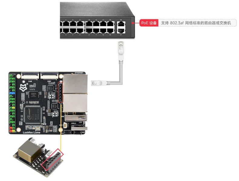
The Luckfox Lume board provides an H1 PoE expansion header. With a compatible PoE module installed, power can be received over an Ethernet cable through the PoE-capable RJ45 port. The module converts it to 5V and supplies the board through VCC-5V-SYS and GND on H1, allowing one Ethernet cable to carry both network data and power.
1. Specifications
| Item | Description |
|---|---|
| Luckfox Lume PoE interface | Onboard H1, 2.54 mm pitch, 6 pins |
| PoE standard | IEEE 802.3af; requires a compatible powered-device module |
| PoE input voltage | Refer to the rated input range of the selected compatible module |
| Module output voltage | 5V DC |
2. Usage
-
Prepare the following:
- Luckfox Lume board;
- A PoE module with a 5V output that matches the Lume H1 pinout and mounting orientation;
- A PoE switch or injector that supports IEEE 802.3af powered devices;
- An eight-conductor Cat5e or higher-category Ethernet cable.
-
Install the PoE module:
- Disconnect all power connections, including Type-C, the 40-pin header, and Ethernet.
- Check the orientation against the H1 pinout and module silkscreen, then install and secure the module.
- Confirm that the module's 5V output connects to H1 pin 5 and GND connects to pin 6.
-
Connect and power on:
- Connect one end of the Ethernet cable to a powered port on the PoE switch and the other to the Lume PoE port routed to H1. Do not assume that both Ethernet ports can receive power.
- Enable power on the switch port and check the board's power and Ethernet indicators.
- The board should boot and establish an Ethernet link. Once it obtains an IP address, you can log in over SSH.
H1 is not a complete PoE powered-device circuit and must be used with a compatible module. Never connect the high PoE voltage from the Ethernet cable directly to the 5V power pin. Unless simultaneous power inputs are explicitly supported, do not connect PoE, Type-C, and 40-pin header power at the same time.
3. Connection Diagram